Three-Phase Inverter System Project
Project Overview
This advanced three-phase inverter system demonstrates power electronics principles using IGBTs (Insulated Gate Bipolar Transistors) and Arduino-based control. The system efficiently converts three-phase AC input to controlled DC, then back to variable frequency AC output, making it ideal for industrial motor control and variable frequency drive applications.
- AC Input: Three-phase AC power input from mains supply
- Rectification: Three-phase rectifier converts AC to DC
- DC Bus: Filtered DC voltage for stable inverter input
- Inversion: IGBT-based inverter converts DC back to controlled AC
- Output: Variable frequency and AC output
- Generates precise PWM gate signals for IGBT switching
- Real-time frequency control
- User interface through push button controls
- Variable Frequency Drives (VFD) for motor speed control
- Industrial automation and process control
- Energy-efficient motor control systems
- Power quality improvement applications
- Educational demonstrations of power electronics
Control Interface
The system features an intuitive control interface with four strategically placed push buttons connected to the Arduino, providing comprehensive control over the inverter operation:
Key Technical Features:
- IGBT Technology: High-efficiency switching with low conduction losses
- PWM Control: Modified square wave
- Variable Frequency: Adjustable output frequency from 30Hz to 70Hz
- Isolation: Proper electrical isolation between control and power circuits
- Real-time Control: Immediate response to user commands
Circuit Diagram & System Components
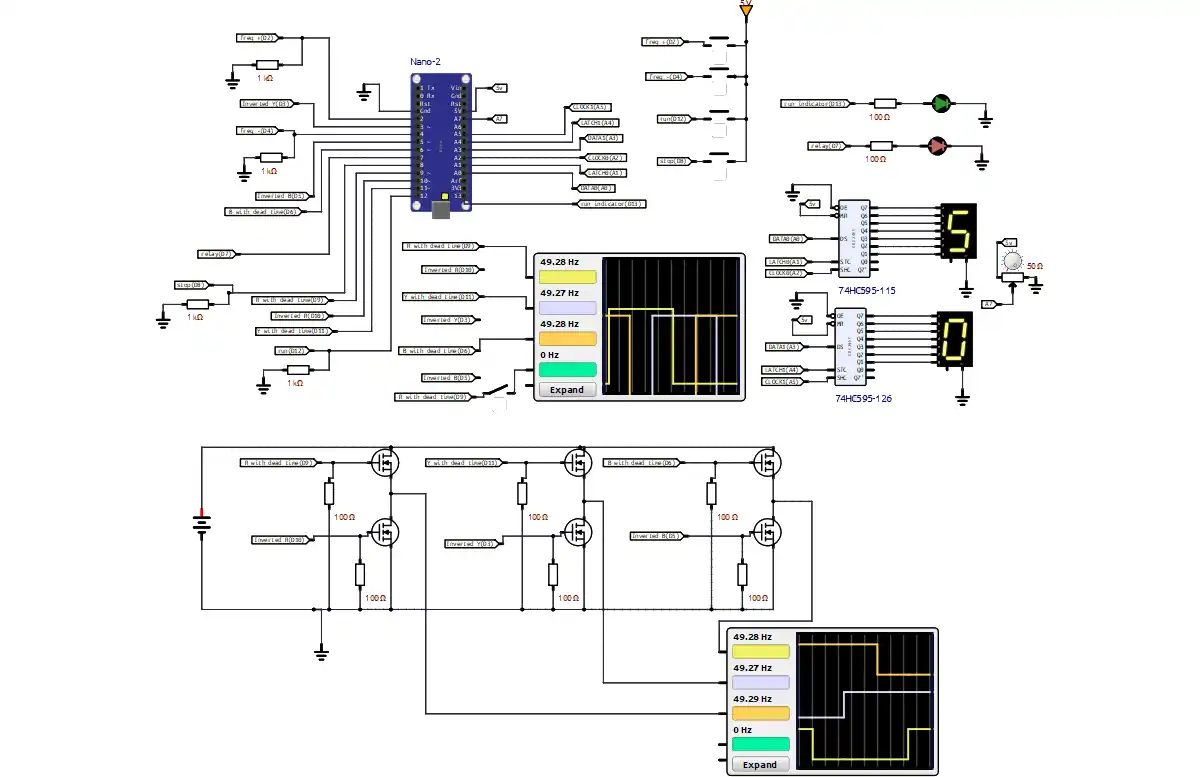
Complete System Circuit Diagram
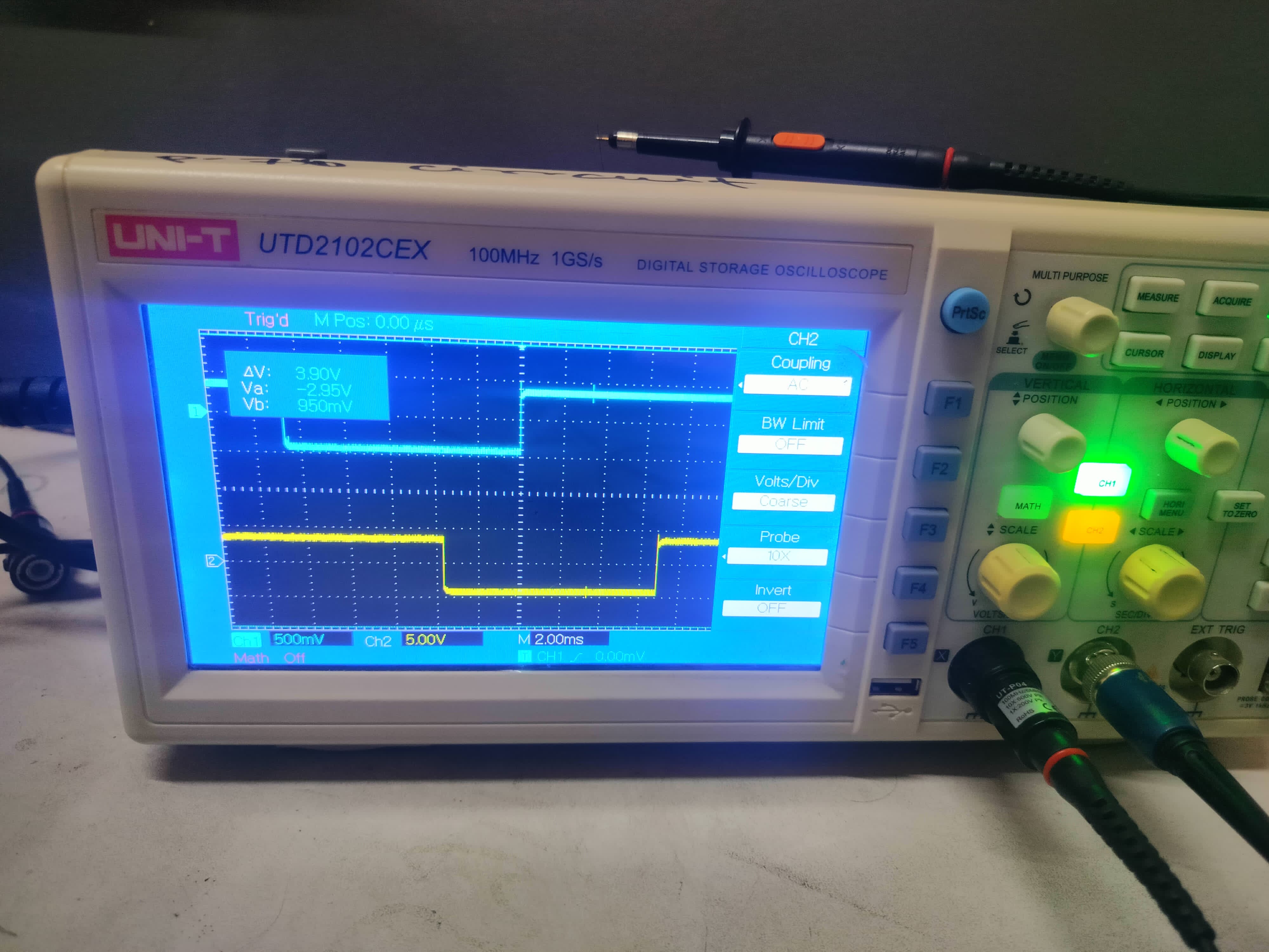
Single Testing using Oscilloscope
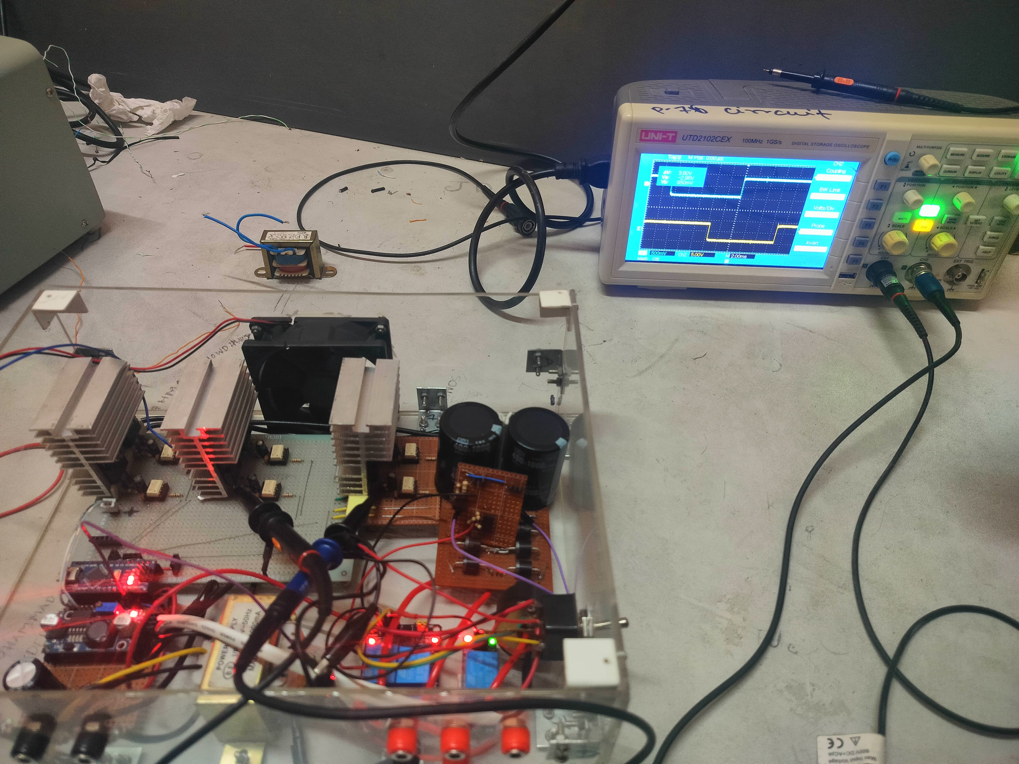
Single Testing using Oscilloscope
Single Testing using Oscilloscope
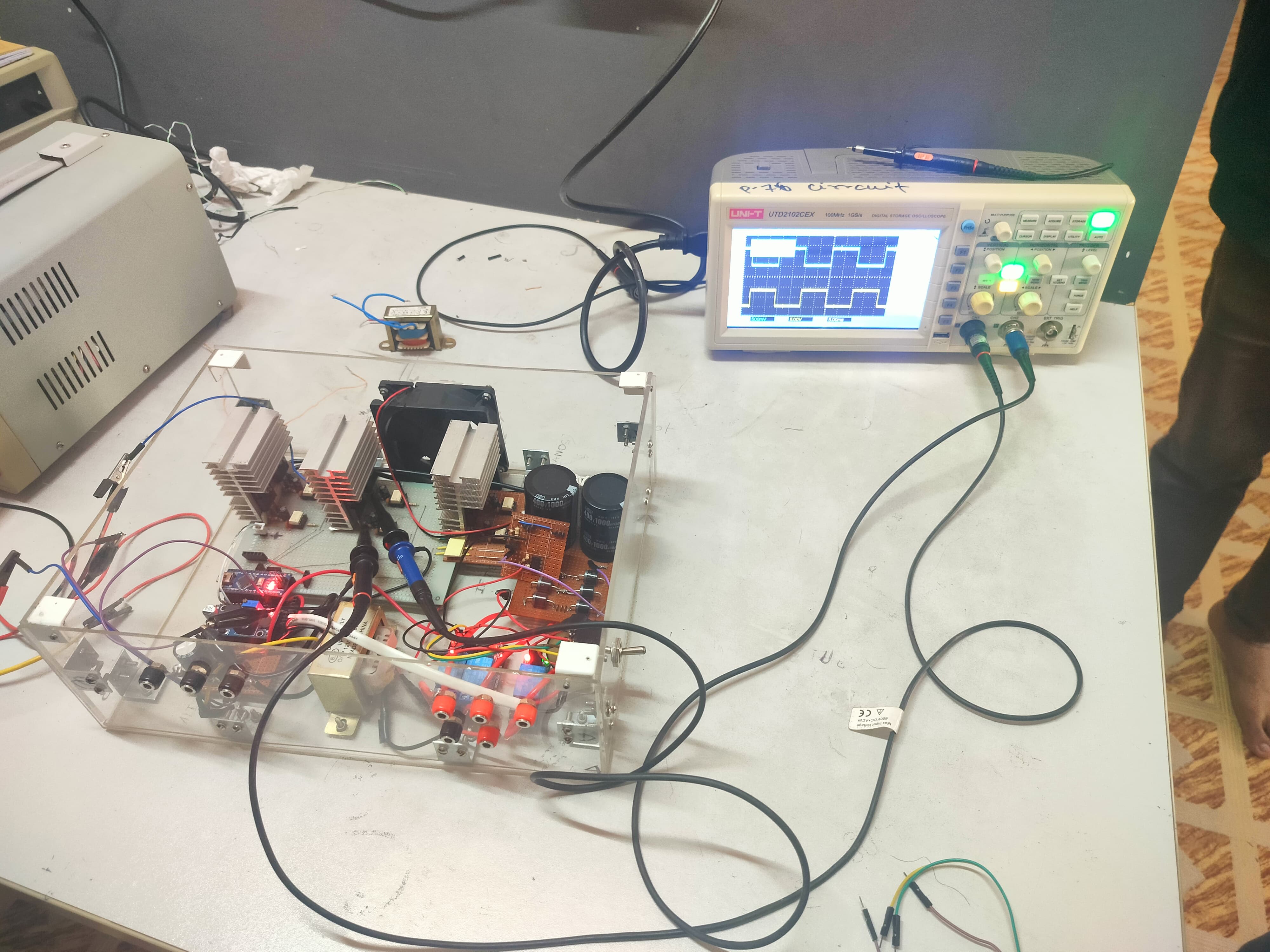
Single Testing using Oscilloscope
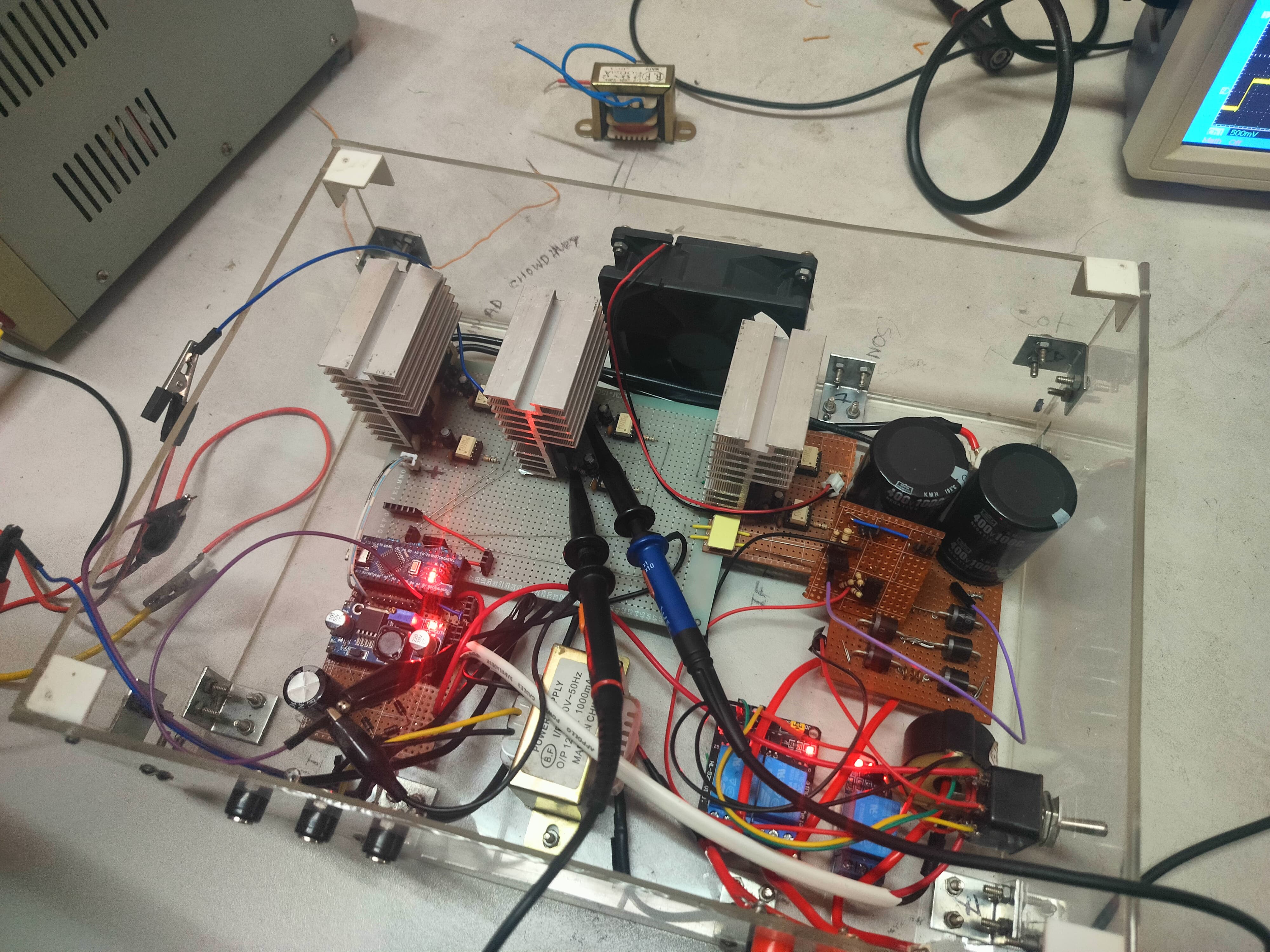
Major Components:
- Arduino Nano: Main microcontroller for system control and PWM generation
- IGBT Modules: Six IGBTs configured for three-phase inverter topology
- Gate Driver ICs: Isolated gate drivers for IGBT control (e.g., IR2110)
- Three-Phase Rectifier: Diode bridge rectifier for AC to DC conversion
- Filter Capacitors: DC bus capacitors for voltage smoothing
- Display: Seven segment display for frequency monitoring
- Push Buttons: User interface for system control
- Heat Sinks: Thermal management for IGBTs
- Isolation Transformers: Electrical isolation for safety
The system architecture demonstrates professional power electronics design with proper isolation, protection, and control mechanisms. The modular design allows for easy maintenance and upgrades.
View Complete Source Code on GitHubProject Demonstration
The demonstration video is currently being prepared and will showcase the complete functionality of the three-phase inverter system.
Planned Demo Content:
- System Startup: Complete power-up sequence and initialization
- Frequency Control: Real-time frequency adjustment demonstration
- Load Testing: System performance under various load conditions
- Waveform Analysis: Oscilloscope readings of input and output waveforms
- Motor Control: Three-phase motor speed control demonstration
The upcoming demonstration will provide comprehensive insights into the system's operation, showcasing both the theoretical concepts and practical implementation of three-phase inverter technology. Stay tuned for detailed performance analysis and real-world application examples.